Diesel locomotive
A Diesel locomotive is a type of railroad locomotive in which the prime mover is a diesel engine. There are several types of diesel locomotive, defined by the method used to convey the prime mover's mechanical power to the driving wheels (drivers).
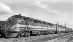
Early internal combustion engine-powered locomotives used gasoline as their fuel. Soon after Dr. Rudolph Diesel demonstrated his first engine in 1893, its application for railway locomotion was considered. Progress was slow until the concept of diesel-electric drive was accepted as a viable power transmission system. By the mid 20th century the diesel locomotive had become the dominant type of locomotive in much of the world, offering greater flexibility and performance than the steam locomotive, as well as substantially lower maintenance costs. Currently, almost all diesel locomotives are diesel-electric.
Contents
History
Adaptation of the diesel engine for rail use
The diesel engine was named for its inventor Rudolf Diesel, who patented his discovery in 1892.[1] The world’s first diesel-powered locomotive was operated in the summer of 1912 on the Winterthur-Romanshorn Railroad in Switzerland, but was not a commercial success.[2]
Adolphus Busch bought the American manufacturing rights for the diesel engine in 1898 but never applied this new form of power to transportation. Only limited success was achieved in the early twentieth century with direct-driven gasoline and diesel powered railcars.[3] General Electric (GE) entered the railcar market in the early twentieth century, as Thomas Edison had an outstanding patent on the electric locomotive, which actually was a railcar.[4] GE built its first electric locomotive prototype in 1895. Because of high electrification costs, they turned to diesel to provide electricity for electric transmission railcars, but issues of co-ordinating the diesel engine and electric motor surfaced. Hermann Lemp, an electrical engineer at GE, developed and patented a reliable Direct Current electrical control system in 1914 which established the basic design for later diesel locomotive control systems. He patented a single control lever that co-ordinated the engine and generator (subsequent improvements were also patented by Lemp)[5]
In 1917, GE produced an experimental diesel-electric locomotive, the first built in the United States. Meanwhile, the 1923 Kaufman Act banned steam engines from New York City. This prompted the electrification of high traffic lines, but was too expensive for lower traffic areas. New York City railroads approached Ingersoll-Rand to build a prototype diesel switching locomotive. GE supplied the traction motors and generator, and the unit was delivered in July 1925, to be used primarily for switching applications. Diesel could provide many of the benefits of electric trains without expensive infrastructure investment.[6]
After Diesel’s patent expired in 1912, diesel engines were successfully used in marine applications; their potential for widespread locomotive use was not initially recognized.[7] In the mid 1920s, Baldwin Locomotive Works produced a prototype diesel-electric locomotive for ‘special uses’ (such as for runs where providing water for steam locomotives was scarce) using electrical equipment from Westinghouse Electric Company.[8] Industry sources were beginning to suggest “the outstanding advantages of this new form of motive power.”[9]
The first regular service of diesel-electric locomotives was in switching applications. General Electric produced several small switching locomotives in the 1930s (the famous "44-tonner" switcher was introduced in 1940) Westinghouse Electric and Baldwin collaborated to build switching locomotives starting in 1929. However, the Great Depression curtailed demand for Westinghouse’s electrical equipment, and they stopped building locomotives internally, opting to supply electrical parts instead.[10] Diesel-electric use entered the mainstream when the Burlington Railroad and Union Pacific used diesel “streamliners” to haul passengers.[3].
Diesel’s advantages over steam
Diesel engines slowly eclipsed those powered by steam as the manufacturing and operational efficiencies of the former made them cheaper to own and operate. While initial costs of diesel engines were high, steam locomotives were custom made for specific railway routes and lines, and as such economies of scale were difficult to achieve.[11] Though more complex to produce with exacting manufacturing tolerances (1/10,000th of an inch vs. 1/100th of an inch for steam), diesel locomotive parts were more conducive to mass production. As such, while the steam engine manufacturer Baldwin offered almost five hundred steam models in its heyday, Electro-Motive offered less than ten diesel varieties. [12]
Moreover, maintenance and operational costs of steam locomotives were much higher than diesel counterparts. Annual maintenance costs for steam locomotives accounted for 25% of the initial purchase price. Spare parts were machined from wooden masters for specific locomotives. The sheer amount of unique steam locomotives meant that there was no feasible way for spare part inventories to be maintained. [13] Steam engines also required large quantities of coal and water, which were expensive variable operating costs. [3] Further, the thermal efficiency of steam was less than that of diesel engines. Diesel’s theoretical studies demonstrated potential thermal efficiencies for diesels of 73% (compared with 6-10% for steam), and his 1897 one-cylinder prototype operated at 26% efficiency. [14] By the middle of the twentieth century, diesel locomotives had effectively replaced steam engines. [3]
United Kingdom
In the 1970s British Rail developed a high-speed diesel-electric train called the High Speed Train or HST. This train consists of two Class 43 locomotives (also known as power cars), one at each end, and a number of "Mark 3" carriages (usually 8). A complete HST set was originally designated as a Class 253 or 254 diesel multiple unit (DMU), but due to the frequent exchanges between sets the power cars were reclassified as locomotives and given class number 43. The unpowered carriages were simultaneously reclassified as individual coaches; the number of a DMU set should identify all its associated carriages as well.
The HST holds the world speed record for diesel traction, having reached a speed of 148 mph, although the operating speed in service is 125 mph (200 km/h), hence the name "Inter-City 125".
Transmission types
Unlike steam engines, diesel engines require a transmission to power the wheels. The engine must be allowed to continue to idle when the locomotive is stopped.
Diesel-mechanical
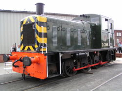
A diesel-mechanical locomotive uses a mechanical transmission in a fashion similar to that employed in highway vehicles. The earliest internal combustion locomotives were gasoline powered, diesel engines first appearing in diesel-mechanical locomotives shortly before World War I.
The mechanical transmissions used for railroad propulsion are generally more complex and much more robust than road versions. There is usually a fluid coupling interposed between the engine and gearbox, and the gearbox is often of the epicyclic (planetary) type to permit shifting while under load. Various systems have been devised to minimise the break in transmission during gear changing, e.g. the S.S.S. (synchro-self-shifting) gearbox used by Hudswell Clarke.
Diesel-mechanical propulsion is limited by the difficulty of building a reasonably sized transmission able to cope with the power and torque required to move a heavy train, but are generally more efficient as transmission losses are reduced [citation needed]. A number of attempts to use diesel-mechanical propulsion in high horsepower applications have been made (e.g. the 1,500 kW (2000 horsepower) British Rail 10100 locomotive), although none have proved successful in the long run. This type of transmission is generally limited to low-powered shunting (switching) locomotives, lightweight multiple units and self-propelled railcars. The Danish IC3 and IC4 railcars use mechanical transmissions for 294 kW (400 horsepower) and 560 kW (750 horsepower) engines respectively.
Diesel-electric
In a diesel-electric locomotive the diesel engine prime mover drives an electric generator whose output provides power to the traction motors. There is no mechanical connection between the prime mover and the driving wheels.
This locomotive type is independent of such fixed power sources as overhead wire (catenary) or electrified rail and hence gives greater flexibility in types of service. Therefore, the diesel-electric locomotive is generally predominant in countries with few electrified railways.
The important components in this system are the diesel engine, main generator (MG or traction generator), traction motors, engine governor, load regulator (LR) and control switchgear. Electrical output from the generator is directed through the switchgear to the traction motors, which are mechanically coupled to the drivers.
Originally, the traction motors and generator were DC machines. Following the development of high capacity silicon rectifiers, the DC generator was replaced by an AC generator using diode bridges to rectify its output to DC. This improved the reliability of the generator, decreased costly maintenance by elimination of the commutator and brushes and allowed the continued use of the existing DC traction motors. Recent developments in high power Variable Frequency / Variable Voltage (VVVF) drives, or “Traction Inverters”, have allowed the use of AC traction motors, thus also eliminating the motor commutator and brushes. The result is a more efficient and reliable drive requiring less maintenance.
Control
The engine’s power output is controlled by varying its rotational speed, American locomotives have 8 fixed speed steps or “notches”, British locomotives had 10.
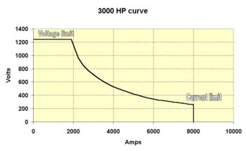
The control system is designed so that the MG output power, for any given engine speed, is a constant. Traction current is highest and voltage lowest at low road speed, as road speed increases the current falls and the voltage rises. Therefore the power remains substantially constant, see diagram.
In older designs the engine governor and the LR play a central part in the control system. The governor has two external inputs; requested engine speed and actual engine speed feedback. The governor has two external control outputs; fuel injector setting and LR position.
The LR is a potentiometer that controls the MG power output by varying its field excitation and hence the degree of loading applied to the engine.
As the load on the engine changes, its rotational speed will also tend to change. This is detected by the governor, as a change in the engine speed feedback signal, which takes corrective action by adjusting both the amount of fuel supplied by the injectors and the LR position. Therefore the engine maintains both a constant power output and rotational speed, regardless of road speed or load changes.
In newer designs controlled by a “traction computer” each engine speed step is allotted an appropriate power output, or “kW reference”, in software. The computer compares this value with actual MG power output, or “kW feedback”, calculated from traction current and MG voltage feedback values. The computer adjusts the feedback value to match the reference value by controlling the excitation of the MG, as described above. The governor still has control of engine speed, but the LR no longer plays a central role in this type of control system. However, the LR is retained as a “back-up” in the event of engine overload. Modern locomotives fitted with electronic fuel injection (EFI) may have no governor, however a “virtual” LR is still retained.
Traction motor speed is controlled either by varying the DC voltage output of the MG, for DC motors, or by varying the AC frequency & voltage output of the VVVF, for AC motors.
DC traction motors, being series wound, draw a large current at standstill. Increasing the MG voltage increases the motor speed, but current decreases due to back EMF. When the MG reaches its maximum output voltage limit no further increase in road speed will be possible. Several methods can be used to extend the operational road speed, all rely on reducing the MG voltage by increasing the motor current;
- Reconnecting the traction motors from a series or series / parallel interconnection to parallel interconnection. This is termed “motor transition”
- Reducing motor field current by means of a switched parallel connected resistor. This increases both the armature's current and speed and is variously termed “field shunting”, “field diverting” or “weak fielding”.
- Reconnecting the two separate internal MG stator windings from parallel to series to increase output voltage. This is termed “generator transition”.
Dynamic braking
A common option on diesel-electric locomotives is dynamic braking, in which the traction motors are re-connected to act as generators. During braking the motion of the locomotive is converted by the traction motors into electrical energy, and dissipated through air-cooled resistor grids located in the top of the hood. The drag thus imparted by the traction motors assists in controlling or reducing the speed of the train, especially on downgrades. When this system assists the regular air brake it is termed "Blended Braking". As the speed decreases the effect of dynamic braking decays; on modern locomotives dynamic braking is usually effective down to about 16 km/h (10 mph).
Electro-diesel
These are special locomotives that can either operate as an electric locomotive or as a Diesel locomotive. The Long Island Rail Road and Metro-North Railroad operate dual-mode diesel-electric/third-rail locomotives between non-electrified territory and New York City because of a local law banning diesel-powered locomotives in Manhattan tunnels. For the same reason, Amtrak operates a fleet of dual-mode locomotives in the New York area. British Rail operated dual diesel-electric/electric locomotives designed to run primarily as electric locomotives. This allowed railway yards to remain un-electrified as the third-rail power system is extremely hazardous in a yard area.
Diesel-hydraulic
Diesel-hydraulic locomotives use hydraulic transmission to convey the power from the diesel engine to the wheels. On this type of locomotive, the power is transmitted to the wheels by means of a device called a torque converter. A torque converter consists of three main parts, two of which rotate, and one that is fixed. All three main parts are sealed in an oil-filled housing .
The inner rotating part of a torque converter is called a "centrifugal pump" (or impeller), the outer part is called a "turbine wheel" (or driven wheel), and between them is a fixed guide wheel. All of these parts have specially shaped blades to control the flow of oil.
The centrifugal pump is connected directly to the diesel engine, and the turbine wheel is connected to an axle, which drives the wheels.
As the diesel engine rotates the centrifugal pump, oil is forced outwards at high pressure. The oil is forced through the blades of the fixed guide wheel and then through the blades of the turbine wheel, which causes it to rotate and thus turn the axle and the wheels. The oil is then pumped around the circuit again and again.
The disposition of the guide vanes allows the torque converter to act as a gearbox with continuously variable ratio. If the output shaft is loaded so as to reduce its rotational speed, the torque applied to the shaft increases, so the power transmitted by the torque converter remains more or less constant.
However, the range of variability is not sufficient to match engine speed to load speed over the entire speed range of a locomotive, so some additional method is required to give sufficient range. One method is to follow the torque converter with a mechanical gearbox which switches ratios automatically, similar to an automatic transmission on a car. Another method is to provide several torque converters each with a range of variability covering part of the total required; all the torque converters are mechanically connected all the time, and the appropriate one for the speed range required is selected by filling it with oil and draining the others. The filling and draining is carried out with the transmission under load, and results in very smooth range changes with no break in the transmitted power.
Diesel-hydraulic multiple units, a less arduous duty, often use a simplification of this system, with a torque converter for the lower speed ranges and a fluid coupling for the high speed range. A fluid coupling is similar to a torque converter but the ratio of input to output speed is fixed; loading the output shaft results not in torque multiplication and constant power throughput but in reduction of the input speed with consequent lower power throughput. (In car terms, the fluid coupling provides top gear and the torque converter provides all the lower gears.) The result is that the power available at the rail is reduced when operating in the lower speed part of the fluid coupling range, but the less arduous duty of a passenger multiple unit compared to a locomotive makes this an acceptable trade-off for reduced mechanical complexity.
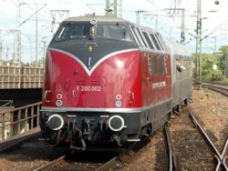
Diesel-hydraulic locomotives are slightly more efficient than diesel-electrics, but were found in many countries to be mechanically more complicated and more likely to break down. In Germany, however, diesel-hydraulic systems achieved extremely high reliability in operation. Persistent argument continues over the relative reliability of hydraulic systems, with continuing questions over whether data was manipulated politically to favour local suppliers over German ones. In the US and Canada, they are now greatly outnumbered by diesel-electric locomotives, while they remain dominant in some European countries. The most famous diesel-hydraulic locomotive is the German V 200 which were built from 1953 in a total number of 136. The only diesel-electric locomotives of the Deutsche Bundesbahn were BR 288 (V 188), of which 12 were built in 1939 by the DRG.
The high reliability of the German locomotives was paralleled by higher reliability of non-German locomotives built with German-made parts compared to that of the same designs built using parts made locally to German patterns under licence. Much of the unreliability experienced outside Germany was due to poor quality control in the local manufacture of engines and transmissions. Another contributing factor was poor maintenance due to staff accustomed to steam locomotives now working on unfamiliar and much more complex designs in unsuitable conditions, and failing to follow the unit-replacement maintenance methods which were part of the German success. It is notable that diesel-hydraulic multiple units, with the advantages of modern manufacturing techniques and improved maintenance procedures, are now extremely successful in widespread use, achieving excellent reliability.
In the 1960s, more than 15 diesel-hydraulic locomotives were purchased by the Denver & Rio Grande and Southern Pacific Railroads on a trial basis from the Kraus-Maffei company. Only the outer shell of one of these (converted into a camera car by SP in the 1970s) exists today, the others having all been scrapped.
Diesel-steam
Diesel-steam locomotives can use diesel or steam power, as needed.
Multiple unit operation
Most Diesel locomotives are capable of multiple unit operation as a means increasing HP and tractive effort with heavier trains. All American, including export models, use a standardised AAR electrical control system using a 27-pin jumper cable between the locomotives. Most UK built locomotives are only inter-operable within their own class.
References
- ↑ Diesel, Rudolf. U.S. Patent No. 608,845, filed July 15, 1895, and issued August 9, 1898
- Accessed via Google Patent Search at: US Patent #608,845 on February 8, 2007.
- ↑ Churella, Albert J. (1998). From Steam to Diesel: Managerial Customs and Organizational
- Capabilities in the Twentieth-Century American Locomotive Industry. Princeton, New Jersey: Princeton University Press, 12.
- ↑ 3.0 3.1 3.2 3.3 Stover, John F. (1997). American Railroads. Chicago, Illinois: The [[University of Chicago
- Press]], 212.
<ref>tag; name "”Stover" defined multiple times with different content Cite error: Invalid<ref>tag; name "”Stover" defined multiple times with different content Cite error: Invalid<ref>tag; name "”Stover" defined multiple times with different content - ↑ Edison, Thomas A. U.S. Patent No. 493,425, filed January 19, 1891, and issued March 14, 1891
- Accessed via the Edison Papers at: US Patent #493,425 on February 8, 2007.
- ↑ Lemp, Hermann. U.S. Patent No. 1,154,785, filed April 8, 1914, and issued September 28, 1915. ::Accessed via Google Patent Search at: US Patent #1,154,785 on February 8, 2007.
- ↑ Churella, 25-27
- ↑ Churella, 15
- ↑ February 18, 1925, "Railroads To Try Diesel Locomotive", Special to the New York Times: 1
- ↑ Churella, 27
- ↑ Churella, 28-30
- ↑ Churella, 10
- ↑ Churella, 19
- ↑ Churella, 12-17
- ↑ Churella, 14
